|
Title: |
1918 Article-Robey & Co. Ltd., Steam Tractor |
|
Source: |
The Engineer, 25 Jan 1918, pg. 65 |
|
Insert Date: |
8/22/2015 9:15:33 PM |
ROBEY AND CO.
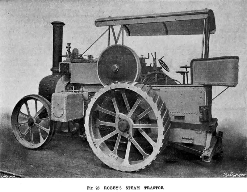
The steam tractor which has been specially designed by Robey and Co., Limited, of Lincoln, to comply with the Heavy Motor Car Act, and for agricultural work is illustrated in Figs. 28, 29 and 30. This handy little engine will haul loads of from 6 to 8 tons on ordinary roads; will plough from 10 to 15 acres of average land per day of ten hours, and will drive such machinery as a 4 ft. 6 in. threshing machine.
The tractor is, as will be observed, of the usual road locomotive type, only, of course, in miniature. The boiler has a heating surface of 81.4 square feet and a grate area of 3.78 square feet. The working pressure is 200 lb. per square inch. The feed pump, which is of the continuous action type, and is driven by gearing at a reduced speed, is ?tted with a return cock, so that the feed water can be accurately regulated by the driver from the foot-plate. There is also a check valve, which is furnished with a shut-off cock, so that all the valves may be examined while steam is up. The pump, which has a delivery chamber ?tted with a relief valve, and renewable gun-metal valves and seats, is arranged in the tender, so as to exhaust steam feed-water heater awn be ?tted if required. To some of the engines, also, Messrs. Robey have ?tted a super heater.
The engine is compound, with cylinders 5 in. and 8¼ in. in diameter by 9 in. stoke. They are combined in one casting, and both are jacketed, the jacket forming a dome through which steam is admitted by the regulator valve to the high-pressure valve chest. The base of the cylinder casting, which is machined, is secured by bolts to a machine-pressed steal seating, which in its turn, is riveted to the boiler. The steam chests are arranged at the sides of the cylinders so as to enable the slide valves to be readily accessible. A Manzel mechanical lubricator and double Ramsbottom safety valves, with an exhaust pipe leading to the chimney, are fitted to the cylinders, and there is also a self-closing auxiliary valve for admitting high-pressure steam to the low-pressure cylinder for use in emergency; for instance, when climbing very steep hills, and also to facilitate starting. The reversing gear is of the Stephenson pattern, and the reversing lever, with its quadrant and notch plate, are arrange on the foot-plate. A fly-wheel of the disc type is keyed to the crank shaft. It is 3 ft. in diameter and 4 in. wide on the face, which is rounded for belt-driving. At this fly-wheel, from 18 to 20 brake horse-power is, we understand, available with the engine running at a speed of 260 revolutions per minute. A governor does not form part of the standard equipment of these tractors, but a high-speed Pickering governor may, if desired, be fitted to act directly on the equilibrium throttle valve in the cylinder casting.
The diameter of the hind traveling wheels is 4 ft. 9 in. and the width of face 12 in., which may be increased to 18 in. by the addition of detachable rings when the tractor is being used for soft ground. The hind axle is of the same diameter throughout, and the arrangement is such that it can be withdrawn without drawing any keys or removing the tender. The end of the crank shaft, which carries the change speed gear, is made square, so as to avoid the necessity for having loose keys. There are two travelling speeds, i.e., 2½ and 5 miles per hour. The change speed gearing is all machine cut, and the throwing in and out mechanism, which is operated by one lever, is so arranged that it is impossible for more than one set of gear to be in mesh at the same time. The whole of the gearing may be disengaged so that the engine may run free. The differential gear, which is provided with four pinions, may be locked if required. The driving disc and differential bevel wheel are pressed on to their keys on the hind axle by hydraulic pressure.
A winding drum is mounted on the main driving disc, on which it can revolve, when a simple locking block has been removed. It contains 50 yards of steel wire rope, which can be paid out as the engine travels forward. The back axle is mounted on Messrs. Robey’s patented spring gear, which embodies a simple and readily accessible wedge adjustment for the laminated spring. A brake, which is actuated by screw mechanism, operated from the foot plate, acts on the rims of both wheels.
Images Courtesy of http://www.gracesguide.co.uk |
|
 1918 Robey & Co. Ltd., Steam Tractor
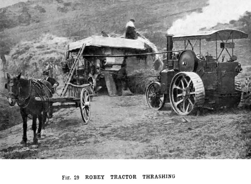 1918 Robey & Co. Ltd., Steam Tractor (Thrashing)
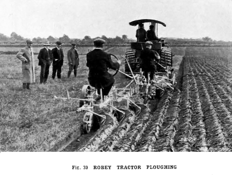 1918 Robey & Co. Ltd., Steam Tractor (Ploughing)
|
|