|
Title: |
1905 Article-Buffalo Forge Co., Tandem Compound Horizontal Steam Engine |
|
Source: |
The Engineer, 01 May 1905, pg., 306 |
|
Insert Date: |
8/15/2015 5:12:37 PM |
AN INTERESTING TEST OF A COMPOUND ENGINE
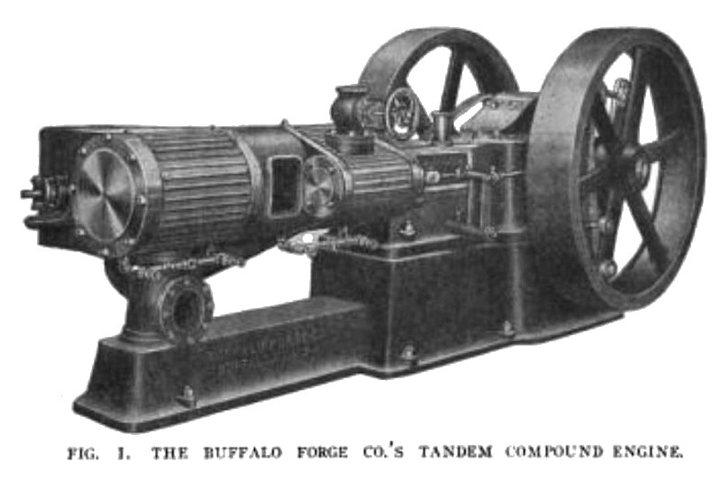
In order to determine the steam consumption, mechanical efficiency and regulation of a Buffalo 12 and 18 x 10-inch horizontal, tandem-compound, high-speed engine, shown in Fig. 1, a test was made at Cornell University by Prof. R. C. Carpenter, assisted by Prof. H. Diedericks.
In this engine, the high-pressure valve takes steam on the inside, and exhausts around the ends. The steam then passes through the cast port in the bottom of the high-pressure cylinder to a receiver pipe on the opposite side, and then to the low pressure valve chest. The steam is led to an exhaust outlet at the bottom of the low pressure valve chest. The high-pressure valve is a piston, while the low-pressure valve is a slide, with a balance plate on the back. The two valves are moved by independent eccentrics and rods, the two eccentrics being on opposite sides of the engine.
Governing is obtained entirely at the high-pressure valve, the motion of this valve being controlled by a centrifugal or shaft governor. The engine, as received, was set to run at about 285 revolutions.
CONDENSER
The engine was connected through about 20 feet of 7 inch exhaust piping, with two elbows, with a surface condenser. A vacuum gage was attached to the condenser about 1 foot from the exhaust inlet. The condenser was in use during the entire course of the test.
During the non-condensing runs, care was taken to keep the vacuum gage exactly at zero, or atmospheric pressure. During the condensing runs, the vacuum was carried as high as possible, which was found to be about 22 inches. Later a leak was discovered in the air pump connections, and when this was closed it was found that the vacuum could be carried as high as 26 inches.
BRAKES
The brakes used were of the well-known Prony pattern. They were constructed of small wooden blocks, placed about 3 inches apart around the surface of the wheels, and connected by three1-inch ropes. These ropes were connected to blocks and tightening screws at the ends, and were screwed up until any desired load was obtained. The brakes were lined with thin sheet iron, and the surface of the wheels was lubricated from time to time with cylinder oil, applied with a brush. The wheels were of the internally flanged type, and the rim was filled with water, and the outside of the brakes wet from time to time with a hose.
Load on the brakes was weighed on a pair of Buffalo scales. The zero weight of the brakes was determined a number of times, by different persons, and found to agree very closely. A man was stationed at each brake with instructions to keep the scale beam of that brake just floating.
INDICATORS
Crosby indicators were used and the indicator motion was one furnished with the engine. It consisted of a small pillar screwed into the frame casting, carrying a shaft which supported a quadrant from which the indicators received their motion. This shaft received its motion from an arm which extended down to a slotted arm screwed to the crosshead.
This form of indicator motion shows some geometrical error, but the error is so small as to have no practical significance. A piece of picture wire was attached to the quadrant, and the indicator springs were hooked to this. The length of string was about 10 inches for the high-pressure, and about 24 for the low-pressure.
For counting the revolutions a small hand speed counter applied to the end of the shaft was used and the speed taken for a full minute each time, the indicator cards being taken during this minute.
LUBRICATION
For this purpose, the engine was well fitted with sight feed oil cups, and the cylinders were oiled by a Nathan sight feed lubricator, applied to the steam pipe just above the throttle valve. The crank case of the engine is arranged as an oil receptacle, and this is filled until the crankpin dips slightly at each revolution, thus ensuring a constant and copious oil supply to the crankpin, main bearings, crosshead, slides and wrist pin.
Stuffing boxes of the piston and valve rods were filled with Garlock packing, which was supplied with the engine, and no difficulty was experienced in packing these boxes, nor in removing the packing from them.
METHOD
In making the test, the method followed was as follows: The engine was started and allowed to run for at least an hour before the actual test was commenced. During this time conditions were adjusted, and at the end of the hour, if conditions were seen to be favorable, the actual test was commenced. The brakes were carefully watched all the time, to see that they held the load constant.
One man was detailed to attend the air pump, and keep the vacuum gage reading constant at the desired figure. One man was detailed to take the indicator cards and the readings from the various gages and calorimeters on the engine, and one to weigh the water and keep the log of the test. The engineer in charge exercised general supervision, and took the revolutions. A preparatory signal was given Yi minute in advance of the time for each reading, and at the exact interval another signal was given, and all observations taken simultaneously. The actual time of each test was 2 hours, this not including the preliminary hour's run.
Readings were taken at intervals of 15 minutes.
Runs were made in the above manner at no load, 30, 60, 90, 120 and 130 horsepower. Rough computations were made during each run of the water rate, and the test was discontinued after the 130-horsepower run, as it was found that at that load the water rate began to rise. The above runs were all made non-condensing.
At the conclusion of this part of the test, additional runs were made at 60 and 120 horsepower, condensing.
INSPECTION AFTER TESTS
Immediately at the conclusion of a run the engine was stopped, the crank cover and side doors removed, the entire engine carefully inspected, and the condition of all bearings noted, the object being to discover any faults that might have developed. In no case could any trouble be detected. At the conclusion of the 130-horsepower run, the engine had been running for about 7 hours, under loads varying from 120 to 130 horsepower, and was not stopped during that time, but no trouble or warm bearings developed.
SPEED REGULATION
One of the builders' latest form of governors was fitted to the engine. The load was applied by means of two planks, used as levers against the flywheel. In this way it was possible to test the governor action under sudden shocks by suddenly applying or releasing the load. By the use of a chronograph it was determined that at 75 horsepower, the regulation was within 0.7 of 1 per cent and at 100 horsepower, within 0.985 of 1 per cent.
STEAM PRESSURE AND QUALITY
Pressure, during all the tests, was kept as close as possible to 125 pounds, but because of changing demands of other machinery connected to the same boiler plant, it varied at times from no to 140 pounds. The pressure was taken from a gage just above the throttle valve.
Quality of the steam was taken with a throttling calorimeter, just before the steam entered the throttle. Steam was found to be nearly dry and saturated throughout the tests.
Fig. 2 shows curves of the steam consumption for noncondensing tests and the mechanical efficiency. Steam consumption is figured for dry steam, the steam being at no time over 4 per cent moisture in the main and usually less than 3 per cent. Curve A shows the relation between developed horsepower and steam per developed horsepower-hour; curve B is between indicated horsepower and steam per indicated horsepower-hour; and curve C is between developed horsepower and mechanical efficiency. |
|
 1905 Buffalo Forge Co., Tandem Compound Horizontal Steam Engine
|
|