|
Title: |
1880 Article-F. and J. Butterfield & Co., Boiler Drilling & Turning Machine |
|
Source: |
American Machinist, 03 Jul 1880, pg. 4 |
|
Insert Date: |
7/18/2015 8:28:47 PM |
Boiler Drilling and Turning Machine
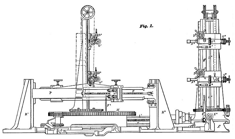
We illustrate herewith a boiler drilling and turning machine, constructed by Messrs. F. & J. Butterfleld & Co., of Keightley, Eng. This machine, says Engineering, has been specially designed for drilling the shells of boilers, and will admit boilers varying from 6 ft. to 10 ft. diameter, and will drill over a length of 6 ft. 6 in at once. The machine is constructed on the patented designs of Mr. John Dickenson, marine engineer and boiler maker of Sunderland, and it is suitable for drilling round, oval or square boilers.
The machine consists of two horizontal bedplates A1 and A', made with V slides on top and placed at right angles to each other. Upon each of the bedplates is fitted a vertical arm B1 and B8, each of which carries two saddles C1 and C2, these being each adjustable vertically on its respective arm by means of rack and pinion and hand wheels D1 and D". The saddles are balanced so that the least possible exertion is sufficient to adjust them. The vertical arms, B1 and B2, are cast each with a round foot by which the arms are attached to the square boxes E1 and E8, which are fitted to the V slides on the horizontal beds A1 and A2, and are adjustable thereon by means of screw and ratchet motion F1 and F2. Each of the square boxes has cast on it a small arm G1 and G2, carrying studs upon which run pinions gearing into the circular racks at the foot of the vertical arms. The square boxes have each a circular groove turned in the top to receive the bolts by which the vertical arms are connected to them, and thus the vertical arms, and with them the drill spindles N1 and N2, are adjustable radially with the boiler—the adjustment being effected by means of the pinions and circular racks. The pinions are arranged so that they can be worked with the same screw key that is used for the bolts in the circular grooves.
The shell to be drilled is placed upon the circular table H, which is carried by suitable framework adjustable by means of screw on a V slide I, placed at an angle of 45° with the horizontal bedplates. By this arrangement, when the table is moved along I, it will approach to or recede from all the drills equally. J1 and J2 are girders forming additional bearings for the framework of the table. The bedplates and slides for the table are bolted and braced together, making the whole machine very firm and rigid. Power is applied to the machine through the cones K1 and K2, working the horizontal and vertical shafts L1 and L2, etc. On the vertical shafts are fitted coarse pitch worms sliding on feather keys, and carried with the saddles C1 and C2, etc. The worms gearing with worm wheels, M1 and M2, are fitted on the sleeves of the steel spindles N1 and N2. The spindles are fitted with self-acting motions O1 and O2, which are easily thrown in and out of gear.
The machine is also used for turning the edge of the flanges, which some makers prefer to have on the end plates of marine boilers. The plates are very readily fixed to the circular table H, and the edge of the flange trued up much quicker than by the ordinary means of chipping. When the machine is used for this purpose, the cross beam P, which is removable, is fastened to the two upright brackets R1 and R2. The cross beam is cast with V slides at one side for a little more than half its length from one end, and on the opposite side for the same length, but from the opposite end. The V slides are each fitted with a tool box S1 and S2, having a screw adjustment for setting the tool to the depth of cut, and adjustable on the V slides of the cross beam to the diameter of the plate to be turned.
This arrangement of the machine is also used for cutting out the furnace mouths in the boiler ends. The plate is fastened to the circular table, the center of the hole to be cut out being placed over the center of the table; one or both of the tool boxes may be used. There is sufficient space between the upright brackets, R1 and R2, to allow that section of a boiler end which contains the furnace mouths to revolve while the holes are being cut out; the plate belonging to the end of a boiler of the largest diameter that the machine will take for drilling. The holes cut out will be from 2 ft. 3 in. diameter and upwards. Power for using the turntable is applied through the cone T. The bevel wheels, worms, worm wheels, and pinions for driving the tables are of cast steel, which is necessary for the rough work of turning the flanges.
As to the practical results of using the machine, the drills are driven at a speed of 340 feet per minute at the cutting edges. A jet of soapsuds plays on each drill from an orifice 1/32 in. in diameter, and at a pressure of 60 lbs. per square inch. A joint composed of two 1-inch plates, and having boles 1 1/8 in. in diameter, can be drilled in about ½% minutes, and allowing about half a minute for adjusting the drill, each drill will do about 20 holes per hour. The machine is designed to stand any amount of work that the drills will bear. The time required for putting on the end of a boiler and turning the flange thereon (say 14 ft. diameter), is about 2½ hours; much, however, depends on the state of the flanges, as sometimes they are very rough, while at others very little is necessary to true them up. The time required for putting on the plate containing the furnace mouths and cutting out three holes 2 ft. 6 in. in diameter, the plate being 1 1/8 in. thick, is three hours. Of course, if several boilers of one size are being made at the same time, the holes in two or more of these plates can be cut out at once. The machine is of such design that it can be placed with one of the horizontal bedplates (say A1), parallel and close up to a wall of the boiler shop; and when the turning apparatus is being used, the vertical arm B2, can be swiveled half way round on its square box E2, and used for drilling and tapping the stay holes in marine boiler ends after they are put together; of course sufficient room must be left between bedplate A2, and the wall of boiler shop parallel with it, to allow for reception of the boiler to be operated upon. Messrs. Butterfield are bringing out apparatus for carrying the boiler during this operation, and which can be used in combination with the shell drill or made into a distinct and separate machine. |
|
 1880 F. and J. Butterfield & Co., Boiler Drilling & Turning Machine
|
|