|
Title: |
1860 Article-S. C. Hills, Morrison's Patent Shingle Machine |
|
Source: |
Scientific American, V 2 #3, 14 Jan 1860, pg. 40 |
|
Insert Date: |
11/25/2014 1:06:55 PM |
IMPROVED SHINGLE MACHINE
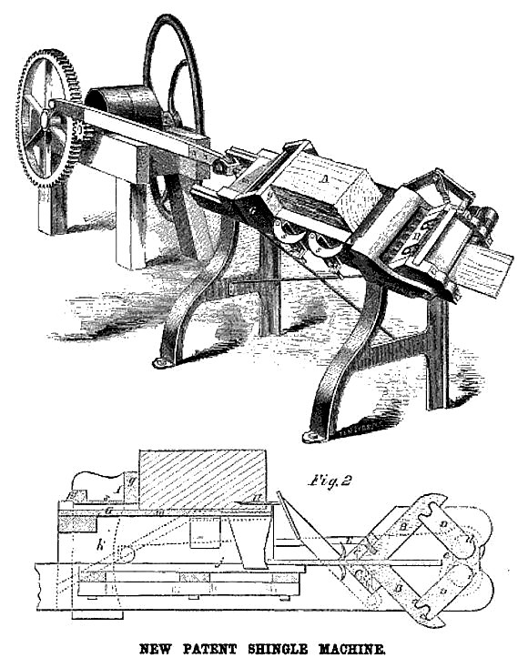
The well established superiority of rived and shaved shingles over those which are sawed and the vast amount of manual labor which is annually expended in shaving shingles by hand, has called forth a great deal of inventive effort to devise some mode of accomplishing the same results by means of machinery. We have seen some large and expensive machines, which made very handsome shaved shingles, but it is of course very desirable to supersede them by others smaller, cheaper and more simple. Such is the object of the invention, which we here illustrate.
A is the bolt from which the shingles are to be rived, previously got out in proper size and form, now placed upon the inclined bed of the machine, as shown. The bolt remains stationary, merely dropping down as the shingles are rived from its lower side, while the knife, H, Fig. 2, is fastened to the right hand end of the bed, in, which receives a reciprocating motion from the crank, r, Fig. 2. The shingle is split off as the knife is being drawn back from the right to the left, dropping down upon the slats, j, ready to be pushed forward through the shaving knives on the return of the bed, m. The slats, j, are about an inch in width and an inch apart, and are stationary, while the reciprocating bed, m, is furnished with similar slats sliding freely between the slats, j. The square ends of the moving slats coming against the end of the rived shingle press it between the planing knives. As the bed, m, moves from the right to the left, the crescent-shaped plates, s s, turn in between the parting shingle and the remainder of the bolt, and support the bolt till the stroke is completed; when the-bed, m, returns from the left to the right it presses the plates, ss, out from beneath the bolt, allowing it to fall down upon the bed, in, in front of the riving knife. In this motion of the bed from left to right, the shingle is planed in the proper wedge shape by being pushed between the knives, C C, which are gradually brought more nearly together during the passage of the shingle. This motion of the knives is effected by bolting them securely to the slides, B B, and imparting to these slides a short reciprocating motion by means of the cranks, D D. These cranks are secured to the axles, d d, which gear together, as shown at e, and receive a rocking motion from the lever, E, shown in dotted lines, which is attached to one of the axles, d. This lever has a forked elbow at its end, which grasps the inclined ledge, g, which ledge is fastened upon the further side of the sliding bed, m, and as it moves along, raises and lowers the end of the lever, thus alternately drawing the knives, C C, apart and pressing them together with great force. By varying the inclination of the different portions of the ledge, g, the shape of the shingle may be regulated at pleasure. These combinations make a compact, simple machine which produces a very handsome shaved shingle. It is complete in itself, requiring no engineering skill to place it, and the several motions are effected by such arrangement as to make them very certain in their relations to each other. The patent for this invention was issued through the Scientific American Patent Agency, Dec. 13, 1859. The inventor is E. R. Morrison, who assigned the in to S. C. Hills, to whom the patent was granted and who may be addressed for further information in relation to the matter at No. 12 Platt Street, this city.
US Patent: 26,463 |
|
 1860 S. C. Hills, Morrison's Patent Shingle Machine
|
|