|
Title: |
1849 Article-Hervey Law, Planing Machine |
|
Source: |
Scientific American, V 5 #36, 26 May 1849, pg. 281 |
|
Insert Date: |
11/6/2014 1:31:42 PM |
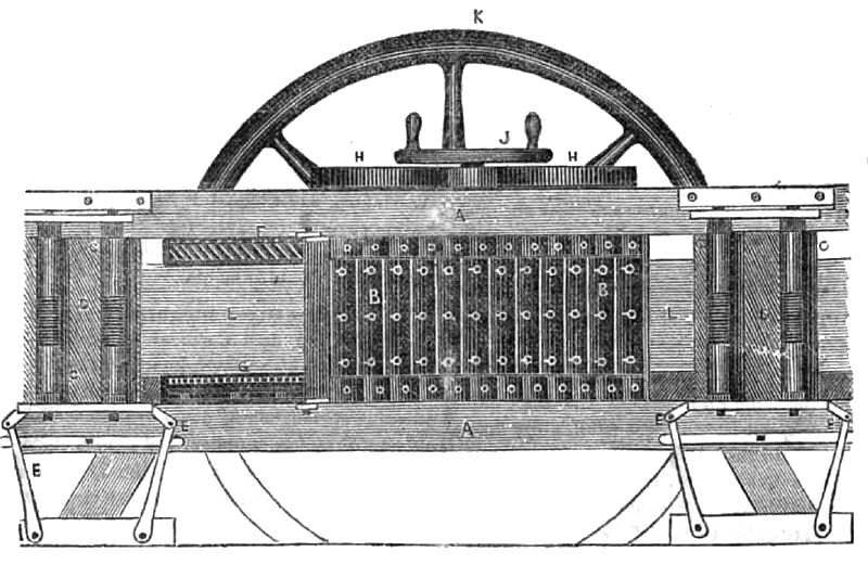
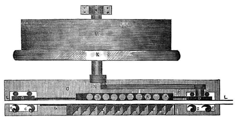
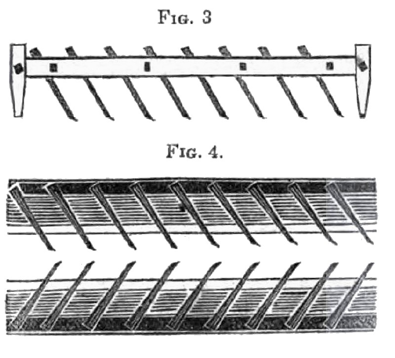
This machine is the invention of Mr. Hervey Law of Wilmington, N. C., the inventor of the Stave Dressing Machine and Jointer, which have appeared in our columns. The invention consists in feeding the boards edgeways to stationary planes and tongueing and grooving cutters, but feeding the said boards in a peculiar manner, to lessen friction and perform work like hand work. Fig. l, is a side view and shows how the board L, is fed In. Fig. 2, is a horizontal section showing part of the frame and the edge of the board, as seen by looking down on the machine. Fig. 3, is a side view of the grooving knives and fig 4, is a side view of the tougueing knives. The same letters of reference indicate like parts. A is the frame work on which the machine is erected. B, is the series of planes secured by screws to triangular blocks as seen i in fig. 2. L L, is ‘the board fed in between the planes B, and friction rollers, R on the other i side opposite the planes, the ends of which are seen in fig. 2. F, fig. 1, are the grooving cutters, (stationary) and G, fig. 2, tongueing cutters, stationary also. Figures 3 and 4, represent the tongueing and grooving knives by themselves, and in fig. 1, they are represented as operating on the board L, after it has been planed.
The feeding is done by reciprocating clamps or tappets, connected to a sliding plate operated by the pitman There are two sets of clamps C, C, one set at the discharge end and the other at the entrance. Fig. 1, shows the position of the feed clamps but fig. 2, shows the form better. C, C, are the clamps and D is a face plate opposite to them secured on the same plate, with a space between for the board L, as seen fig. 2. These clamps with the plates have a reciprocating motion communicated by the connecting rod P, from the crank N. G, is a correcting rod, which from P, moves the discharging clamps. E E, fig. 1, are flexible arms, like parallel rulers, secured to pivots below, and to the axis of the plates have a reciprocating motion communicated by the connecting rod P, from the crank N. G, is a correcting rod, which from P, moves the discharging clamps. E E, fig. 1, are flexible arms, like parallel rulers, secured to pivots below, and to the axis of the clamps above to give them a steady reciprocating motion. 0, is the bed-plate on which the feed motion is secured. K, is a flywheel, and M, fig. 2, a drum to drive the machinery by hand. On fig. 1, there is a small wheel J, secured on a small vertical shaft, on which is a pinion that meshes into cog wheels H H.-
On the shafts of these cog wheels under the ends of the planes are two cams which increase or lessen the distance between friction rollers R R, and the planes B B, to suit the planing operation to hoards of different thicknesses. Set screws may also be used for this purpose.
From the engravings presented and the description given, a knowledge of the principles of this machine’s operation will be imparted to our readers. We have endeavored to do this clearly, by presenting views that would show its operation In the simplest manner. Mr. Law now resides in this city, No. 216 Pearl street. |
|
 1849 Article-Hervey Law, Planing Machine
 1849 Article-Hervey Law, Planing Machine (Horizontal Section)
 1849 Article-Hervey Law, Planing Machine (Tongue & Grooving Knives)
|
|