|
Title: |
1895 Article-Pratt & Whitney Co., Rogers-Bond Comparator |
|
Source: |
Modern Mechanism 1895 pgs 496-499 |
|
Insert Date: |
6/21/2011 8:25:35 PM |
The Rogers-Bond Comparator—From a lecture delivered at the Franklin Institute in 1884 by Mr. George M. Bond, the head of the gauge department of the Pratt & Whitney Co,. who was associated with Prof. Rogers in the design and construction of the comparator, we abstract the following description: "The special features of the universal comparator are, as its name implies, the variety of the methods employed and the range of work that can be done in comparing standards; each independent method, when carefully carried out, producing similar results, which serve to check or prove the comparisons. It includes a method for investigating the subdivisions of the standard by comparing each part of the total length with a constant or invariable quantity or distance." Referring to the illustrations (Figs. 7, 8, 9), the main features of its construction are the following: "A heavy cast-iron base, A. is mounted upon stone-capped brick piers, giving a permanent foundation to the apparatus. Upon this base, and reaching from end to end, are two heavy steel tubes, B and C, 3 in. in diameter, ground perfectly straight, and being ‘true’ when placed in the centers of a lathe, the object being to get a straight-line motion of the microscope-plate D, which slides freely on these true cylinders. Flexure of these cylindrical guides is overcome by lever-supports at the neutral points n and n'. Fitted closely to these guides and outside of the range of motion of the microscope-plate D are two stops, E and F, one at each end, as shown in the figure. These stops are arranged to be adjusted at any desired position along the guides, and are securely held by clamping on the under side by the handles O and H. These stops are each provided with a pair of electro-magnets, 1 and J, the poles of which do not quite come in contact with the armature seen at either end of the microscope-plate. Contact is made at K and L, which are hardened steel surfaces, tempered and polished, and placed as nearly as possible in the center of mass of the plate and of the stops. The magnets are intended to overcome the unequal pressure due to ordinary contact, a rack and pinion being used to move the plate. The magnets are used to lock the microscope-plate at each end of the traverse between the stops. The use made of this sliding microscope-plate and the stops we shall see presently. Beyond the main base just described, and supported also on brick piers, is an auxiliary heavy cast-iron frame N, which is provided with lateral and vertical motion within the limits of zero, and of 8 and 10 in. respectively, for rough or approximate adjustment, and upon the top of this frame are two carriages, 0 and 0', which slide from end to end. a distance of about 40 in. Upon these sliding carriages are placed tables T and T1, provided with means for minute adjustment, for motion lengthwise, sidewise, and for leveling, thus permitting the adjustment of a standard yard-bar quickly, and without the necessity of its being touched with the hands after being placed upon the table until the work of comparison is completed. "The first operation in the use of this form of comparator is to level the main base A (Fig. 9), then sliding the microscope-plate D from end to end of the steel tubular guides, having the microscope adjusted so as to be in focus upon the surface of mercury contained in a shallow trough, over which the microscope passes, the curvature due to flexure of the guides is determined, and may be compensated for by counter-weights at the neutral points of support, n and n'. In order to test this right-line path of the microscope-plate horizontally, the method of the 'stops' is employed, or, another method, which is that of tracing a fine line the entire length of a standard bar upon its upper surface, and, reversing the bar, tracing another line very near the first, and at an equal distance opart at each end ; then, if this distance is uniform between the two lines the entire length, it is safe to assume that the path of the plate is a straight line horizontally, and at the middle the amount of curvature, if any, and if uniform, is readily determined. This method is used by Prof. Rogers with complete success. The 'stop method' is to compare a line-measure or an end-measure bar, on each side of the center line of motion of the microscope-plate, using one microscope, and comparing this fixed length with the constant quantity before referred to, which is the distance between the stops. Should the path be a curved one, the distance between the defining lines upon the bar will appear greater on one side than on the other, in proportion to the amount of curvature existing. The length of the standard, being the length of chords of circles of different radii, seems, by comparison with the stops, to be different in length at each position, caused by the different distances from the center of curvature—about 18 in. in this instance—over which the microscope passes when placed in these two positions. By means of the proportion of similar triangles thus formed, the length of the radii may be very accurately determined. By placing different standards on one side of the line of the stops, they may be, by being compared with a constant quantity, compared also with each other.
"Another method for comparing two or more standards is to place two microscopes, one on each of two microscope-plates, upon the guides, at a distance determined by the length of one of the standards, and by replacing this one by a second, the coincidence of the lines in the eye-piece micrometer, or their variation, showing at once their relation. The microscopes may be placed horizontally in this same fixed relation, using the method invented by J. Homer Lane, and which has been successfully used in the office of the United States Coast Survey at Washington.
"The subdivision of these standards of length, which is effected by the use of this same process—the microscope-plate sliding between fixed stops. This is accomplished in the following way: A yard, for instance, is to be subdivided into three equal parts, or into three separate feet. We divide the whole length by trial into three parts, then, by setting the stops so that the microscope-plate may move very nearly the distance represented by the first one of the three parts, by readings of the eye-piece micrometer carefully taken at each end of the path of motion of the microscope, and using the finely ruled lines by which these three parts are defined, we obtain the length of this subdivision as compared with our constant quantity; then, by sliding or moving the bar along under the microscope until the second part is in place, the same operation is again performed, and so for the third, thus determining the relation of each with respect to this temporary or arbitrary standard; then, by adding the differences between these separate parts and the constant length, and taking the mean or average of these differences, from which we subtract each difference, gives us the correction to be applied to each part in order that it shall be exactly one third the total length, or, as in case of a yard-bar, giving us exactly 12 in., or the standard foot. The foot may then be subdivided in the same manner into 12 equal parts, establishing the standard inch, and, further, to 1/8, 1/16, 1/32, 1/100 or even to 1/1000 of an in." (See Trans. Am. Inst. Mech. Engrs., vol. iv., 1882.) |
|
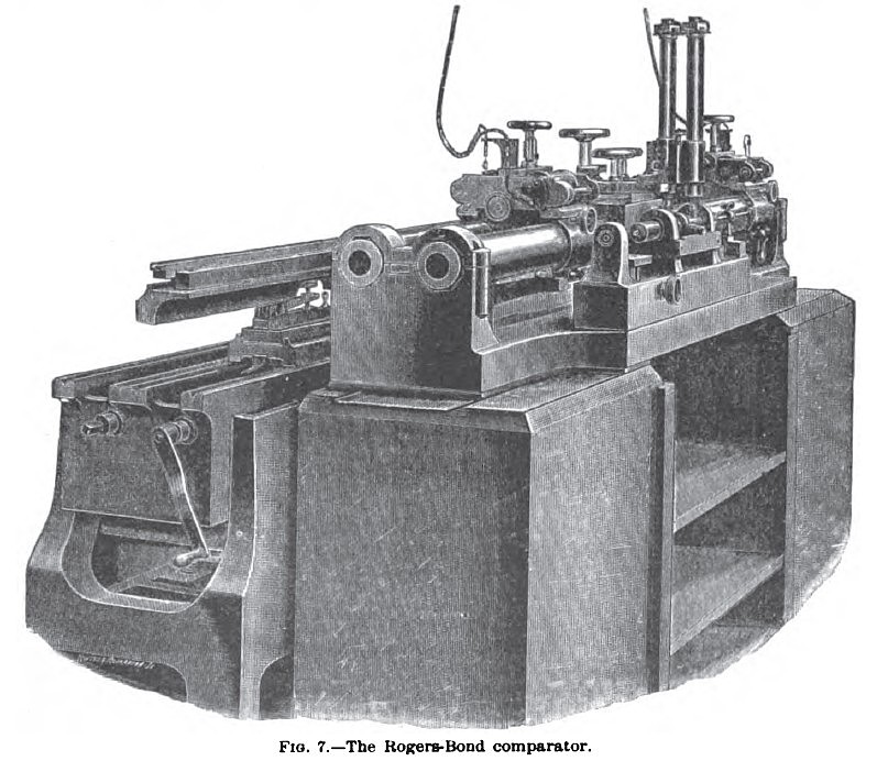 1895 Pratt & Whitney Co., Rogers-Bond Comparator
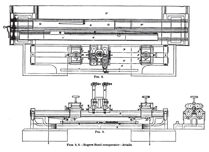 1895 Pratt & Whitney Co., Rogers-Bond Comparator Details
|
|