|
Title: |
1900 Image-Morton Mfg. Co. Traveling Head Draw-Cut Shaper |
|
Source: |
Machinery Magazine Jul 1900 pg 326 |
|
Insert Date: |
4/17/2025 11:48:51 AM |
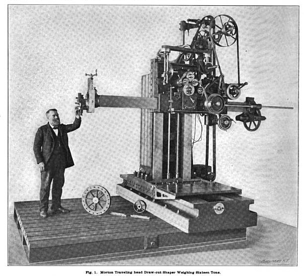
LARGE TRAVELING-HEAD SHAPER.
The shapers made by the Morton Manufacturing Co., Muskegon Heights, Mich., have the distinguishing characteristics that they operate on the pull or draw-cut principle, the cutting stroke being during what is ordinarily the return stroke in the common type of shaper. The effect of this construction is to draw together the different parts of which the shaper is composed-to close the joints, as it were-while the cut is in progress, and the harder the machine is worked, the closer the parts are drawn together and the more rigid the tool. An unusually long shaper ram can be used without vibration when operated on this principle.
For reasons that will be obvious, this construction is peculiarly adapted for large and heavy work, as, for example, castings that are so large that they cannot be conveniently placed on the planer, but which have short faces or bearings to be faced off. Some very heavy machines have been constructed by the Morton Manufacturing Co. for such work, some of which are of a portable type, to be set on any floor plate on which the work happens to be located, and others of which are attached to their own floor plate. One of the latter class is shown in the accompanying illustration.
This machine has a floor plate 9'x10' 6", provided with T-slots, on which the work to be operated upon is placed. The bed is attached to the floor plate at right angles with the T-slots, and is heavily ribbed and cross-ribbed. A horizontally moving vertical column is gibbed and fitted to the bed, while the head carrying the shaper ram is capable of moving vertically upon the column.
This column is provided with square rail bearings, and upon it is located a vertically moving saddle or apron to which are attached the entire operating mechanisms of the shaper. The front side of the vertical column is also provided with a T-slotted plate. A brace can be placed between this plate and the work, thus holding the work rigidly when under heavy cuts. This column is also heavily ribbed and cross-ribbed, the metal being so distributed as to form the most substantial construction.
The vertical movement of the machine is 48 inches, logitudinal feed 78 inches, and it will admit of 6 feet between the ram and floor plate. Its total height is 13 feet and it weighs complete about 16 tons.
The ram is made of steel cast hollow, carefully fitted, and provided with wedge gibs for taking up wear. The machine obtains its reciprocatory motion through two friction clutches located on either side of the gearing and belted with an open and crossed belt from the countershaft, the ratio being such that the ram has a quick return of three to one. The friction clutches are positive in their movements and therefore the cutter will work close to a line and will carry a heavy cut. The shaper feed is operated by a self-driving friction. The feed screws are both stationary, the nuts revolving, they being fitted with ball-bearing thrust collars. It will be readily seen that by using the crank on the right-hand shaft, the apron of the shaper is made to raise and lower on the column, and by turning the left-hand squared shaft, the column is fed longitudinally on the bed. By this arrangement both feeds are entirely under control of the operator. The stroke is adjusted by means of tappets on a circular disk, and there is a lever conveniently placed for the operator, for reversing at any point of the stroke. The driving gearing is all cut from the solid, and is encased and runs in oil.
An interesting and unusual feature of this machine is a milling attachment that is designed for facing in a plane perpendicular to the line of direction of the ram. This attachment consists of a steel arbor passing through the ram, which has a train of gearing at the rear end and which can be easily removed by the operator when it is not desired to use it. The cutter head used on the milling attachment is seen lying on the floor plate of the machine. Power for milling is supplied through a cone pulley and bevel gears to a splined shaft which engages the gearing at the rear end of ram. It is belted direct from the countershaft and has two changes of speed. The feed when used for milling is taken direct from the cone pulley by belting to the encased mitre gearing and through the cone pulleys to the friction disk and can be regulated by raising and lowering the friction wheel which engages the disk and can be reversed by moving to the opposite side. Connected with the shaft of this friction disk are a worm and gear by which power is applied directly to the feeding shafts. It will be readily seen that this provides a continuous feed in either direction, enabling the use of a tool in the form of an ordinary milling head by which chipping strips and pieces can be faced from the sides of large castings. The machine is also provided with a friction clutch by which the countershaft can be stopped and started independently of the motor, and with this device, when moving the machine either vertically or horizontally by power, the machine itself remains idle. The vertical saddle is counter-balanced and power is applied through an endless belt, direct from the motor, which is so arranged that as the tool raises and lowers it does not affect the tension of the belts.
The machine is electrically driven but can be furnished to be driven with a belt if so desired. It will be readily seen that the operator can adjust the stroke, control the feed, motor, and the entire machine from the platform made for this purpose.
As mentioned above, the machine is also constructed so that it can be easily detached from the bed and can be used in connection with an ordinary floor-plate as a portable machine on heavy castings. It can also be provided with a small table of the ordinary box type, which can be bolted to the floor-plate and made of convenient height, upon which small work can be placed. In this way the machine will work successfully on small
pieces as well as large. The floor-plate can also be constructed with a vertical floor-plate in connection with it, in a pit, so that by moving the machine to the front side of the floor-plate, heavy castings can be operated upon which could not otherwise be reached. |
|
 1900 Morton Mfg. Co. Traveling Head Draw-Cut Shaper
|
|