|
Title: |
1903 Article-H. W. Ward & Co., Cutter Grinder |
|
Source: |
Emery Grinding Machinery, 1903, pgs. 134-137 |
|
Insert Date: |
12/3/2015 7:30:16 PM |
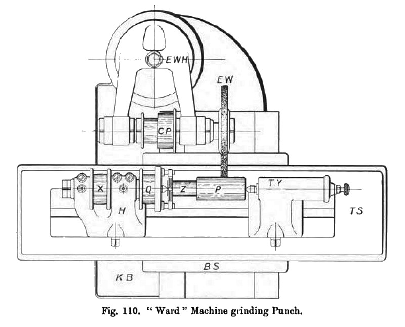
An example of grinding a drawing punch is seen in plan fig. 110. As this is an instance of external cylindrical grinding, it will be noticed that the universal chuck seen in fig. 109 has been removed to allow of the special bronze bushed pulley Q being put into place, and the tailstock T Y has been fixed in a position for receiving the drawing punch P. In this example the spindle and pulley X remain stationary in the head H, whilst the pulley Q drives the punch V on dead centres by means of the studs and plates. These plates, which act as carriers or drivers, are shown fixed to the shank Z of the punch, while the emery wheel E W is grinding the punch P parallel to some definite diameter. These drawing dies and punches are usually bored or turned, as the case may be, to their exact finished size whilst they are in the soft state, and it is a frequent occurrence for them to warp slightly whilst undergoing the hardening and tempering process. It is on this account that the grinding machine is so valuable for dealing with drawing tools, because the hole in the die may be left slightly smaller in diameter when being bored, or the punch left larger when being turned, until they have been hardened and tempered. They can afterwards be ground perfectly smooth and to size by means of the emery wheel.
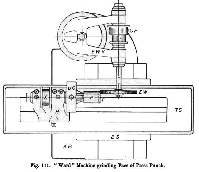
The plan fig. 111 shows the emery wheel head E W H in the same position as it was in fig. 108, but in fig. 111 the knee bracket K B has been raised higher up the column to bring the centre of the work head spindle level with the centre of the external grinding spindle; the cylindrical cutting punch P is chucked by its shank in the universal chuck U C, whilst the edge of the emery wheel operates upon the face F of the cutting-out punch. |
|
 1903 H. W. Ward & Co., Cutter Grinder
 1903 H. W. Ward & Co., Cutter Grinder
 1903 H. W. Ward & Co., Cutter Grinder
|
|