|
Title: |
1856 Article-Nelson Barlow, Wood Planing Machine |
|
Source: |
The Engineer Magazine, 01 Feb 1856 pg. 60 |
|
Insert Date: |
12/16/2014 11:28:50 AM |
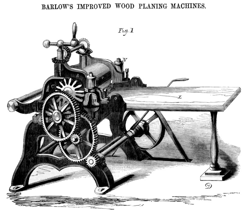
The accompanying engravings are views of the improved Wood Planing Machine for which a patent was granted to Nelson Barlow, on the 1st of July last.
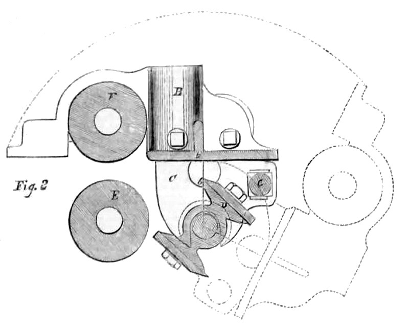
Figure 1 is a perspective view of the machine, and fig. 2 is a section exhibiting the radical action of the upper frame and connections.
The general principle of the invention consists in passing planks over a cylindrical cutter of the usual form, which revolves in fixed journals in the frame of the machine, and over a fixed roller or bed in front of the cylinder, while the planks are pressed down by an improved self-adjusting frame acting upon their upper sides, and they are, by this means, brought to a uniform thickness.
A is the main frame of the machine. It has suitable bearings to receive the shaft of the cutting cylinder, D, fig. 2, which is armed with cutters of the common form, and which revolve and cut in a direction against the advance of the plank. Inside of the bearings of cylinder D, there are other large bearings that receive a projecting hollow axle, formed upon the sides
of the standards, C, through the centre of which the shaft of the cylinder passes.
B is an upper frame attached to and resting upon standards, C, C. This frame can be raised and depressed by adjusting screws to set it, for planks of various thicknesses. It has a plate, b, at its lower part, extending from side to side between the standards; this plate bears upon the surface of the plank while being planed. In the forward part of frame B, the upper driving roller, F, is placed, its under side being in a true line with the plate, 6. The under driving roller, E, is parallel with the first, and is attached to the main frame in an unyielding position. After the plank passes the cutting cylinder, and has been reduced, it rests upon and is supported by the small roller G. As this roller is connected with standards, C, and they being connected to the cylinder shaft by a hollow axle, it follows that this roller occupies a fixed relative position to the under side of the plank and to the cylinder; no adjustment of it, therefore, is necessary for planks of different thicknesses. A bar may be used in place of this roller, or the table may extend out from the machine to f-support the planks. L is the feeding table, the part, O, to which it is attached, is connected with the cross rail of the main frame on an axle, by which it can be moved up or down, or it may be connected with the shaft of the lower roller. H, fig. 1, is a connection or link which, through the medium of the rubber spring, N, attaches the upper frame, B, to the lower frame, A. By the elastic pressure of this link, it controls the action of the upper frame, giving such an amount of bearing force upon the plank as may be necessary. This link has a lip at its lower edge that fits into a recess in the part O, and there is a recess on its upper part to match it into the frame, B. These connections arc removed when the cutters require to be sharpened; this leaves the frame, B, free to be swung over, and when in this position the cutters can be sharpened or adjusted with ease.
"When a plank enters the feeding rollers, F, E, the upper one rises (being under elastic pressure) as the forward part of the upper frame rises. The frame, B, together with the plank, is then inclined, which incline is greater or less, according to the surplus wood of the plank. As the plank passes forward from the rollers, its upper side rests against the bearing plate, b, with a considerable pressure, because the weight of the plank acts upon the lower roller as a lever, and also because of the inclined position of the plate. This prevents the cutters from taking too deep a hold and marring the ends of the plank on entering the machine. In passing out of the machine, the small roller, G, acts as a similar agent in connection with the weight of the plank, to keep the rear end of the plank in firm contact with plate 6. The driving rollers occupy at all times parallel positions, thereby bearing equally upon the plank, thus exerting a uniform feeding force.
This planing machine differs from some others by being arranged to plane the lumber upon its under side. The cutting cylinder is thus enclosed, which removes to a great degree the annoyance from dust and liability
to accident, and which also saves the surface of the plank from being marred by indentations from the chips, &c, and prevents, by the upper frame, B, their ends from being scored on entering and leaving the cutters. The feeding rollers, E and F, have fixed bearings, the former upon the main frame, A, and the latter in the self-adjusting frame, B, which frame is held down by the springs, N N, to the plank. The frame, B, is connected with the stands, C, which are attached to the frame, A, by means of axles around the shaft of the cutting cylinder, and can be swung over readily upon these centres whenever it is desirable to obtain access to the cutters for sharpening, &c, as stated. Changes of thickness are made in the most convenient manner, by raising or depressing the upper frame, which is alone adjustable, and the machine is thus reduced to the smallest possible number of adjustable parts.
The space occupied by the machine is small, being only about four by three feet, and the power required to operate it is comparatively trifling, it is especially adapted as a shop machine, where it Is desirable to save power and room. It will plane lumber twenty-two inches in width and under, and from one fourth to two and one-half Inches in thickness.
One of these machines is on exhibition at the Fair of the American Institute, in the Crystal Palace, and more information may be obtained by letter, addressed to Alfred Conger, agent, 345, Broadway, this city.—Scientific American. |
|
 1856 Nelson Barlow, Wood Planing Machine
 Wood Planing Machine (Cutter-Head)
|
|